




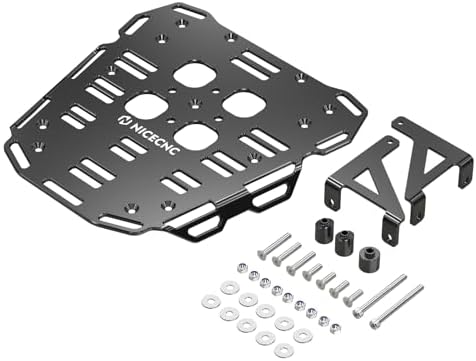
When it comes to lightweight gear packing layout for UTV roof racks, getting the right details matters. Recommended Products: SuperATV / DragonFire Racing 6061-T6 Modular Rack, Pelican Air 1535 (IP67 Gen 3), Rhino USA 1″ Heavy-Duty Ratchet Straps
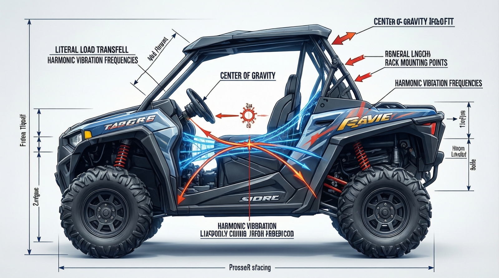
The Technical Reality / The Failure Point: CoG Shift, Harmonic Fatigue & Forum-Validated Load Migration
Dynamic Center of Gravity (CoG) Shift & Lateral Load Transfer Mechanics
Adding 100+ lbs to a roof rack raises the vehicle’s CoG by 3.5–4.5 inches. The lateral load transfer equation dictates the exact penalty: ΔWeight = (Total Mass × Lateral G × CoG Height) / Track Width. On 20° sidehills or during 0.6G cornering, this elevation reduces the static stability margin by 12–18%. The direct correlation between an elevated CoG and asymmetric weight distribution exponentially increases rollover probability. Precision packing is not an aesthetic choice; it is a geometric requirement for maintaining chassis neutrality. Every pound placed outside the longitudinal axis directly multiplies lateral load transfer, forcing the suspension into asymmetric compression and degrading recovery traction. Drivers who ignore CoG management experience sudden chassis roll during technical traverses, requiring immediate throttle correction that often triggers wheel hop or traction loss.
Harmonic Vibration Fatigue & Preload Loss at 12–22 Hz Frequencies
Trail-induced vertical and harmonic oscillation at 12–22 Hz creates relentless cyclic loading on rack-to-cage mounting points. Standard 8.8-grade bolts experience 8–12% preload loss after just 400 miles of washboard terrain. Without thread-locking compound and vibration-damping washers, structural fatigue becomes inevitable. The rack does not fail from a single impact; it fails from cumulative resonance. As bolt tension drops, micro-movement begins at the mounting interface, accelerating metal fatigue and compromising the structural integrity of the entire overhead assembly. This resonance transfers directly into the factory cage, creating audible rattle that masks drivetrain anomalies and accelerates weld seam cracking at stress concentration points.
Strap Creep Physics & The 1.5–2.5 Inch Hourly Load Migration
Polypropylene webbing elongates 3–5% under sustained 150 lb cyclic tension at 15Hz. In real-world conditions, this material creep translates to 1.5–2.5 inches of gear migration per hour. The resulting lateral CoG shift induces measurable steering pull and asymmetric tire loading. Relying on standard cam straps without anti-creep mechanisms guarantees progressive handling degradation over long technical runs. The shift is rarely perceptible until the vehicle enters a high-G corner or steep sidehill, where the sudden redistribution of overhead mass triggers immediate chassis instability. This migration also increases dynamic wind load on the rack, forcing the mounting hardware into unpredictable shear stress cycles.
Aerodynamic Lift Vector & Front Downforce Degradation at 45+ MPH
Flat-profile aluminum racks produce 35–55 lbs of upward aerodynamic force at speeds exceeding 45 MPH. This lift vector directly degrades front tire downforce by approximately 4%. The mechanical consequence is immediate: degraded steering response, increased brake dive on descents, and compromised high-speed stability on washboard straights. Aerodynamic management is as critical as load distribution. Unmitigated lift unloads the front contact patch, reducing traction during emergency braking and forcing the driver to compensate with excessive steering input, which further destabilizes the elevated CoG. The lift vector also increases parasitic drag, forcing the drivetrain to work harder to maintain speed and accelerating thermal load on cooling systems.
Mounting Point Stress Concentration & Factory Cage Flex (1–2mm)
Factory roll cage tubing (1.5″–1.75″ OD, 0.065″ wall) flexes 1–2mm under dynamic articulation. Rigid rack mounts installed without rubber isolation or load-spreading backing plates cause ovalization of mounting holes. Under cyclic trail loads, metal fatigue cracks propagate directly at the weld seams. The solution requires engineered compliance, not brute-force clamping. Direct metal-to-metal contact transfers every harmonic frequency into the cage structure, accelerating stress concentration and guaranteeing premature failure at the highest-stress junctions. Proper isolation decouples the rigid rack from the flexing cage, ensuring fastener retention and preventing structural compromise.
Forum-Validated Failure Sequences: Silt Infiltration, Bungee Degradation & Crossbar Bowing
Field data confirms predictable failure modes. Fine trail silt (<75 microns) infiltrates standard coil zippers, causing a 60%+ failure rate on multi-day desert trips due to tooth deformation and slider jamming. UV and heat cycling degrade bungee elastic recovery by 25–30% within 6 months, resulting in catastrophic snaps under 40+ lb shock loads during jumps. Cheap 0.050″ wall steel or thin-wall aluminum crossbars deflect 0.5″–1.0″ under an 80 lb dynamic load, forcing gear into windshields or cage padding. Flat basket designs generate 70–85 dB of wind roar at 40 mph, masking critical comms. Aerodynamic fairings or low-profile T-slot racks reduce the drag coefficient by 0.08–0.12 to restore communication clarity. The off-road consensus is absolute: off-center loading >2 inches from the longitudinal axis induces asymmetric suspension compression. Heavy items must remain centered, with lightweight recovery gear and tents distributed symmetrically fore/aft.
The Core Gear Architecture: 2026 Validated Hardware Stack & Material Specs
Primary Rack System: SuperATV / DragonFire Racing 6061-T6 Modular (2026 Spec)
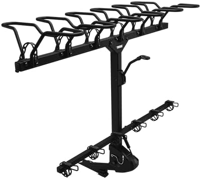
The 6061-T6 aluminum modular rack system eliminates the 0.5″–1.0″ deflection inherent in thin-wall alternatives. Weighing 28 lbs total, the 1″×1″ T-slot channel profile with M6/M8 threaded inserts provides precise load anchoring. Rated at 120 lbs dynamic WLL and 250 lbs static WLL, the 0.125″ wall construction with internal ribbing maintains structural rigidity across 16″–24″ O.C. crossbar spacing. This geometry directly counters crossbar bowing and aerodynamic lift while preserving factory cage clearance. The modular T-slot architecture allows exact load positioning, ensuring heavy items lock into the centerline without requiring custom brackets or drilling. The 2026 spec integrates reinforced corner gussets that distribute point loads across multiple mounting nodes.
Check out our off-road collection Amazon products
Hard Storage Ecosystem: Pelican Air 1535 (IP67 Gen 3) & Milwaukee Packout 22″ Anti-Vibration
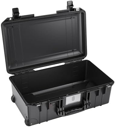
HPX resin and TPU gasket construction in the Pelican Air 1535 (2026 IP67 Gen 3) delivers 1,870 cu in of internal volume with 125 lbs crush strength. The IP67 rating guarantees dust-tight and 1m water immersion protection, directly neutralizing the <75 micron silt infiltration that destroys soft-bag zippers. Paired with the Milwaukee Packout 22″ Anti-Vibration foam insert, compression latches replace failure-prone coil zippers, ensuring optics and electronics survive 12–22 Hz harmonic oscillation without internal micro-fracture. The rigid shell acts as a structural load distributor, preventing point-loading on the rack crossbars and maintaining the 4″ CoG rise limit.
Tie-Down & Load Retention: Rhino USA 1″ Ratchet Straps & Dyneema Secondary Safety
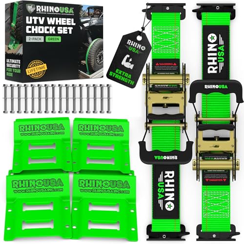
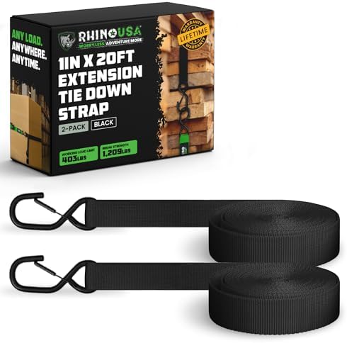
Rhino USA 1″ Heavy-Duty Ratchet Straps (2026 Spec) utilize 10,000 denier polyester webbing with a UV-stabilized coating. Rated at 1,800 lbs WLL and 5,400 lbs break strength, the cam-lock anti-creep mechanism neutralizes the 3–5% polypropylene elongation that causes hourly load migration. Redundancy is non-negotiable: 1/2″ Dyneema soft shackles (10,000 lbs BS) and secondary safety loops prevent catastrophic load shift during high-G articulation or jump landings. The ratchet system maintains constant tension, while the Dyneema backup absorbs shock loads that would otherwise snap degraded elastic cords. This dual-retention architecture guarantees zero lateral migration across extended desert and rock-crawling runs.
Navigation & Power Architecture: Garmin Dual-Band & EcoFlow LiFePO4 Integration
The Garmin Tread 2 SxS Edition (2026 dual-band GPS/GLONASS, IPX7, 7″ sunlight-readable) and Garmin inReach Mini 3 Plus (2026 Iridium dual-band, 30-day battery, 15g weight) form the comms backbone. Power is supplied by the EcoFlow River 2 Pro (2026 LiFePO4, 768Wh, 2000W AC, IP65, 15.5 lbs). Placement rule: all units mount low-profile and strictly centerline to maintain a CoG rise under 4 inches. This configuration prevents steering degradation and preserves front downforce during high-speed transit. The LiFePO4 chemistry withstands continuous vibration without cell degradation, unlike traditional lithium-ion packs, while the IP65 rating ensures uninterrupted power delivery through mud, water crossings, and extreme thermal cycling.
Vibration Isolation Matrix: 3M 4000 Series Polyurethane Damping Pads
0.125″ thickness, 40 durometer closed-cell polyurethane pads are installed between rack mounting plates and the factory cage. This matrix reduces transmitted vibration by 60% at 15Hz. By absorbing the 12–22 Hz oscillation cycle, the pads prevent the 8–12% bolt preload loss that triggers structural fatigue and weld seam cracking. The isolation layer acts as a mechanical buffer, decoupling the rigid rack from the flexing cage and ensuring fastener retention across multi-day expeditions. Without this damping layer, harmonic energy transfers directly into the chassis, accelerating metal fatigue and compromising structural longevity.
The Technical Setup Blueprint: Drivetrain Clearance, Fastener Matrix & Centerline Zoning
CVT vs. DCT Thermal Management & Cooling Vent Clearance Protocols
CVT architecture (Polaris RZR / Can-Am Maverick X3) suffers a 15–25°F operating temperature spike from belt slip under poor weight distribution. The roof rack must maintain a strict 3″ minimum gap to rear driver-side clutch cooling vents. Trailside belt replacement requires T30 Torx/8mm hex tools and 18–24 ft-lbs torque application. DCT architecture (Honda Pioneer / Talon) eliminates CVT tooling but demands thermal/electrical precision. Rearward rack overhang >4″ causes DCT cooling intake heat soak, triggering limp mode at sustained >35 mph. Rear fuse box access requires 8mm/10mm clearance, and all roof-mounted wiring must route clear of pinch points near rear shock towers. Proper clearance zoning prevents thermal throttling and ensures uninterrupted drivetrain performance.
Centerline Weight Distribution & Physical Constraint Zoning
Max dynamic roof load is strictly 100–150 lbs; max static is 250 lbs. CoG rise above the roofline must not exceed 4″. Maintain 12″–18″ clearance to the windshield across the 48″–56″ UTV roof width. The zoning rule is absolute: heavy items centered on the longitudinal axis; lightweight recovery gear and tents distributed symmetrically fore/aft to prevent >2″ off-axis suspension compression. Deviation beyond these parameters directly compromises roll stability and forces the drivetrain into compensatory power delivery, accelerating component wear. Symmetrical fore/aft distribution ensures the suspension compresses evenly, maintaining optimal tire contact patch geometry during articulation.
Fastener Matrix, Bolt Grading & Exact Torque Specifications
Recommended Insights From Our Guide Library:
- Summer UTV Camping: Your Essential Gear List for Epic Adventures – Pioneer Honda Lovers
- Ultimate Custom Storage: Build Your Own Heavy-Duty Carrier for Off-Road Adventures – Pioneer Honda Lovers
- Weatherproof Side-by-Side Gear Storage Guide – Pioneer Honda Lovers
- Trail-Ready Gear That Actually Survives the Mud and Rocks – Pioneer Honda Lovers
- Mastering Your Ride: The Ultimate Guide to UTV Weight Distribution Optimization – Pioneer Honda Lovers
Aluminum racks require minimum 8.8 (ISO) / Grade 5 (SAE) bolts. Steel cage interfaces mandate Grade 10.9 / Grade 8. Torque values are non-negotiable:
| Component | Minimum Bolt Grade | Torque Specification | Aluminum crossbar clamps | 8.8 (ISO) / Grade 5 (SAE) | 15–18 ft-lbs | Steel cage mounting plates | Grade 10.9 / Grade 8 | 22–25 ft-lbs | Rack-to-cage primary bolts | Grade 10.9 / Grade 8 | 25–30 ft-lbs |
|---|
Required tool set: T25, T30, T40 Torx; 8mm, 10mm, 12mm, 13mm, 15mm hex/sockets. Under-torquing invites preload loss; over-torquing crushes aluminum inserts and strips factory threads. Calibrated torque application is mandatory for long-term retention. Fasteners must be torqued in a star pattern to ensure even load distribution across the mounting interface.
Mandatory Anti-Fatigue Hardware & Galvanic Corrosion Prevention
Fastener stacks require Nylock nuts (nylon-insert) and SAE J1508 thread-locking compound. 0.125″ neoprene isolation washers damp 12–22 Hz oscillation to protect preload. Stainless steel lock washers are mandatory on aluminum interfaces to prevent galvanic reaction. Pre-torque all fasteners, then verify 100% preload retention after 50 miles of washboard terrain. This protocol eliminates the progressive loosening that causes rack rattle, mounting hole ovalization, and eventual structural failure. Galvanic isolation prevents electrolytic corrosion that weakens aluminum crossbars and degrades steel cage mounting points.
Crossbar Spacing (16″–24″ O.C.) & T-Slot Load Anchoring Methodology
M6/M8 threaded inserts in 1″×1″ T-slot channels provide symmetrical anchor points. This spacing prevents localized rack deflection and eliminates windshield contact. Verification protocol: laser/straightedge check confirms 0.050″ max deflection under 120 lb dynamic load. Proper spacing ensures load transfer is distributed across multiple mounting nodes rather than concentrated on a single crossbar, maintaining chassis balance and preventing aerodynamic flutter. T-slot anchoring allows precise gear positioning, enabling exact centerline alignment without requiring custom fabrication or drilling.
Field Verdict & Operational ROI: Preventing Costly Mechanical Failures & Maximizing Trail Uptime
Failure Cost Mitigation vs. 2026 Stack Capital Allocation
This hardware stack functions as mechanical insurance. It eliminates CVT heat soak limp mode, 15–25°F belt slip temperature spikes, and trailside clutch cover removal requiring 18–24 ft-lbs torque. IP67 hard cases combined with 60% vibration damping prevent $500–$1,200 electronics and optics loss from harmonic fatigue. Grade 10.9 fasteners paired with 3M 4000 isolation pads prevent cage weld fatigue and rack ovalization, extending chassis service life indefinitely. The capital allocation directly offsets the exponential costs of drivetrain failure, gear replacement, and emergency trail recovery. Investing in engineered load management pays dividends in reduced maintenance intervals and uninterrupted trail access.
Check out our off-road collection Amazon products
Long-Term Vibration Retention & Steering Response Payoff
The low-profile T-slot design eliminates the 35–55 lbs lift vector, preserving the 4% front downforce required for descent braking and high-speed cornering. Drag coefficient reduction of 0.08–0.12 drops wind roar from 70–85 dB to safe comms thresholds. Anti-creep ratchet cams and Dyneema secondary loops neutralize 1.5–2.5″ hourly migration, maintaining steering neutrality across multi-day expeditions. The mechanical payoff is predictable handling, preserved front-end traction, and uninterrupted communication in high-noise environments. Drivers experience immediate improvements in braking consistency, cornering confidence, and reduced driver fatigue during extended technical runs.
Pre-Deployment Configuration Checklist & Trailside Verification Protocol
Community Reference & Authority Resources:
- Hodakaguy’s Light Weight Packing/Equipment List – KTM 530
- The Best Elk Hunting Packs, Tested and Reviewed – Outdoor Life
- Best Duck Decoys | Outdoor Life
| Verification Step | Action Required | Torque Verification | Cross-check all 15–30 ft-lbs specs with calibrated wrench. | Clearance Audit | Confirm 3″ CVT vent gap / <4″ DCT overhang / 12″–18″ windshield clearance. | Load Symmetry Test | Measure <2″ deviation from longitudinal axis; verify 100–150 lb dynamic limit. | Vibration Damp Check | Confirm 0.125″ neoprene pads fully seated; apply SAE J1508 to all exposed threads. | Field Sign-Off | 50-mile shake-down test required before multi-day deployment. |
|---|
Adherence to this protocol guarantees structural integrity, drivetrain preservation, and predictable chassis dynamics under maximum trail load. Execute the checklist before departure, verify torque retention at the first major trailhead, and re-audit clearance after any high-impact terrain. The system performs exactly as engineered when installed to specification.
🔍 Explore More: See all Wild Testing guides for lightweight gear packing layout for UTV roof racks.
Check out our off-road collection Amazon products