
I. Introduction: Embracing the Complexity of Modern Power
The modern 4-stroke engine found in high-performance ATVs and UTVs (such as the Can-Am Renegade or Polaris RZR) represents a significant evolutionary leap from its 2-stroke predecessors.
Rebuilding a 2-stroke top end was often a rapid task—remove the cylinder, hone the bore, slap in new rings, and ride.
Today’s 4-stroke machines, however, are sophisticates, high-tech pieces of racing hardware.
They incorporate complex valvetrain components, including camshafts, timing chains, and multiple valves, requiring a dramatically increased level of precision and attention during any internal service.
For the dedicated enthusiast, mastering this complexity is often a necessity.
While professional labor costs for an engine rebuild average around $800 or more, performing the job personally can reduce the cost significantly (often $500 to $800 in parts alone).
However, the process demands more than basic mechanical skill; it requires disciplined measurement and adherence to factory specifications.
A lack of precision in clearance setting or tightening sequence can quickly lead to catastrophic engine failure.
The engine builder must prioritize proactive maintenance to avoid reaching the point of total destruction.
Modern high-performance motors are fragile and require keen attention.
Waiting until the engine is size or billowing dramatic black smoke is the worst-case scenario, as the damage may necessitate expensive machining like cylinder sleeving rather than simple replating or component replacement.
Utilizing an hour meter to track wear and planning preventative maintenance, such as changing a sport ATV piston after approximately 50 hours, significantly mitigates the risk and cost of a major overhaul.
II. Phase 1: Preparation, Safety, and Mandatory Tooling
A. Diagnosis and Timing
Before initiating the teardown, a thorough diagnosis is essential to confirm the need for a rebuild.
Common indicators that an ATV or UTV engine is nearing the end of its serviceable life include a significant lack of power, especially under load;
persistent blue or white exhaust smoke, which signals oil consumption due to damaged piston rings or valve wear;
odd internal noises such as tapping, knocking, or grinding;
and excessive oil consumption requiring frequent top-offs.
A compression test and leak-down test are the most accurate diagnostic methods to gauge internal engine health.
B. Workshop Safety and Cleanliness Protocol
Meticulous preparation is the first line of defense against contaminants.
The mechanical area must be secure, with clear hazards remove, and the engine allowed to cool completely before work begins.
Mandatory Personal Protective Equipment (PPE) includes safety glasses and durable gloves to protect against grit, springs, and chemicals. Proper ventilation is critical when working with degreasers, fuels, and engine gases.
Prior to any disassembly, the entire machine should be washe to prevent dirt from falling into critical orifices.
During disassembly, an air gun is an exceptionally useful tool for blowing debris out of tight spots, such as spark plug holes, before removing the plugs.
Cleaning techniques are time-consuming but highly rewarding.
Engine cases and components should be treat with a powerful degreaser to remove built-up oil and grime.
Components exposed to rust should be treat with chemical removers or a wire brush.
The inspection process that follows cleaning is crucial: every piece, from the cylinder head to the balance shaft and cases, must be examin under magnification for imperfections before reassembly.
C. The Hierarchy of Specialty Tools
While a basic mechanic’s toolkit containing metric wrenches, sockets, and screwdrivers is necessary , deep internal engine work requires specialized equipment.
These specialty tools are mandatory because engine building operates at tolerances far tighter than general maintenance, demanding precise torque and micro-level measurement.
A quality Torque Wrench is non-negotiable.
Because powersport engines operate under high vibration and high load, they are finely turn by manufacturers who mandate precise torque specifications for engine-related components.
Using a standard ratchet creates a safety hazard, increases the risk of mechanical failure (such as cylinder head warping or stripped threads), and voids any warranty.
Other essential specialty tools include those required for measurement and extraction:
Essential Specialty Tools for Precision Engine Rebuilding
| Tool Category | Purpose | Why It’s Mandatory |
|---|---|---|
| Torque Wrench | Achieving manufacturer-specified fastener tension. | Prevents cylinder head warping and guarantees component longevity. |
| Micrometer & Dial Bore Gauge | Measuring bore roundness, taper, and piston diameter. | Determines precise piston-to-cylinder wall clearance to 0.0001”. |
| Flywheel/Clutch Puller | Safe removal of flywheel/clutch components. | Required for bottom-end access; avoids damage to expensive components. |
| Piston Ring Compressor | Guiding ring sets safely into the cylinder bore. | Ensures rings are compressed evenly without breakage. |
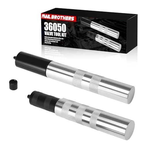
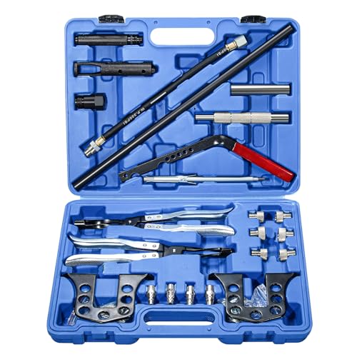
| Valve Spring Compressor | Disassembling and assembling the cylinder head valvetrain. | Required for safe installation/removal of valve springs and keepers. |
Model-specific tools, such as flywheel pullers and clutch pullers, are often necessary to access the bottom end of the engine on platforms like the Polaris RZR or various Can-Am models without damaging expensive drive components.
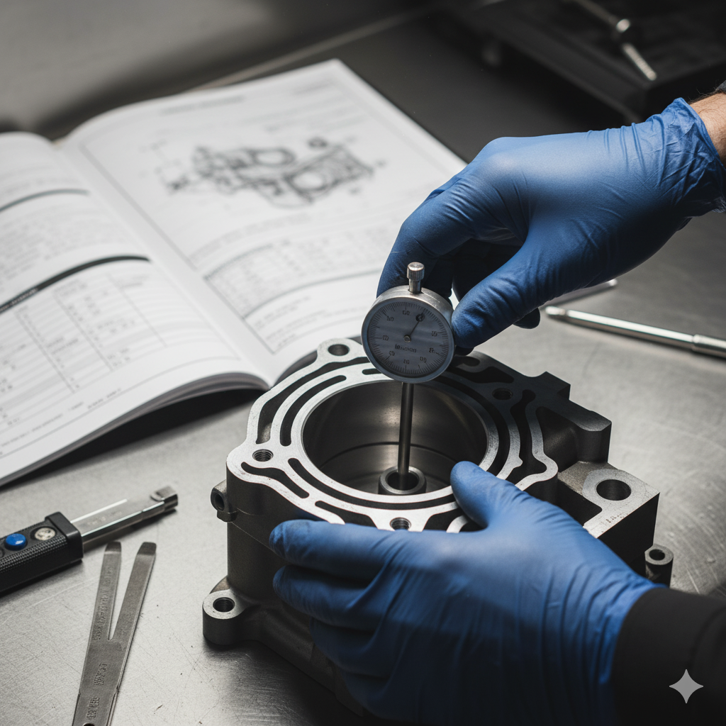
III. Phase 2: Mastering Precision Measurement and Clearances
Engine longevity and performance are inextricably tied to component clearances.
Failing to verify tolerances—such as piston-to-cylinder clearance or valve lash—is a common error that ensures catastrophic failure.
Therefore, the builder must treat the manufacturer’s service manual (OEM, Clymer, or Haynes) as the definitive authority for all dimensional specifications, torque values, and procedures.
A. Cylinder and Piston-to-Bore Clearance
The accurate measurement of piston-to-bore clearance determines how well the piston will seal and manage heat inside the cylinder.
This requires the combined use of two precision instruments:
the outside micrometer and the dial bore gauge.
- Micrometer Application: The outside micrometer is use first to measure the piston skirt diameter. Micrometers offer accuracy down to 0.0001 inch or one-thousandth of a millimeter and must be used on clean parts and surfaces.
- Bore Gauge Application: The dial bore gauge does not provide an absolute measurement; rather, it measures the difference between the known piston diameter and the cylinder bore diameter. The gauge must first be “zero” or set to the precise piston skirt measurement taken by the micrometer. The bore gauge is then run down the cylinder bore at multiple points (top, middle, bottom) and in different orientations to check for taper (variation in diameter) and out-of-roundness. This calculation confirms that the clearance is within the factory specification required for piston thermal expansion and oil film thickness.
B. Piston Ring End Gap
Piston rings must be individually check for proper end gap before installation.
This is achiev by sliding each ring squarely into the cylinder bore (it is recommende to use the bottom of the bore where wear is minimal) and measuring the gap with a feeler gauge.
If the gap is too small, a specializ piston ring filer must be used to carefully increase the gap to specification.
If the gap is too large, the ring set is incorrect for the bore size.
C. Bearing Oil Clearance Assessment
For measuring crankshaft main and connecting rod bearing clearances, two distinct methods exist, differentiated by the required level of accuracy.
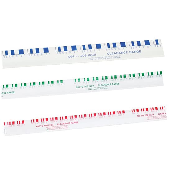
The most accessible method is the use of Plastigage.
Plastigage is a useful, low-cost diagnostic tool for stock or lower-stress engine freshening.
The procedure involves cutting a short length of the Plastigage material and placing it on the clean crankshaft journal.
The bearing cap is then install (dry) and torqued precisely to the manufacturer’s specification.
Upon removal of the cap, the resulting width of the crushed Plastigage is compared against a scale printed on the packaging to determine the clearance.
However, for high-performance builds, particularly those that operate at high pressures and speeds, Plastigage provides only a visual check, not the high degree of accuracy necessary.
These engines are often set up on the “razor’s edge” of serviceable limits, requiring adjustments in tenths of thousandths of an inch.
In these cases, the bore gauge and micrometer are mandatory, measuring the inside diameter of the bearing shell/tunnel and comparing it precisely to the crankshaft journal diameter.
Critical Clearances and Measurement Techniques
| Clearance Requirement | Measurement Tools | Reference Check | Risk Assessment |
|---|---|---|---|
| Piston-to-Bore | Micrometer (Outside) & Dial Bore Gauge | Piston skirt diameter vs. Cylinder bore diameter. | Highest risk: Leads to immediate scoring, power loss, and engine seizure if incorrect. |
| Bearing Oil Clearance | Plastigage (or Micrometer/Bore Gauge set) | Crushed plastic strip compared to packaging scale. | High risk: Low oil pressure, premature bearing/crankshaft failure under load. |
| Piston Ring End Gap | Feeler Gauge | Ring placed squarely in bore. | Medium risk: Loss of compression, excessive blow-by, or potential ring breakage. |
IV. Phase 3: Flawless Assembly and Torque Discipline
The execution of the assembly phase must be flawless, as errors here immediately negate the work performed in the measurement phase.
The risk associated with 4-stroke complexity is multiplicative; mistakes in valvetrain assembly (cam timing, valve lash) can lead to instant, total destruction from valve-to-piston contact.
A. Assembly Lubrication Protocol
Prior to the installation of any moving parts, all friction surfaces—including piston skirts, ring surfaces, crankshaft journals, and camshaft lobes—must be coated with a dedicated engine assembly lubricant or high-viscosity break-in oil.
This specialized lubricant provides a protective film to prevent scoring and friction during the initial dry start-up and critical break-in period, ensuring components are protected until the engine oil has established full pressure and circulation.
A critical choice that impacts long-term engine health is the operating oil itself.
Powersports enthusiasts must never use standard automotive motor oil.
High-performance ATV/UTV engines utilize specific oil formulations designed to deal with meshing gears (which shear the long polymer molecules found in conventional oils) while maintaining adequate protection under high RPM and temperature extremes.
High-quality synthetic oil designed for powersports applications is mandatory.
B. Piston Ring Installation and Clocking
Proper piston ring installation is essential for compression and oil control.
Rings must be installed from the bottom of the piston up.
Most rings have an identification mark, often the word “TOP” or a dot, which must face toward the top of the piston (usually toward the intake side).
For the three-piece oil ring, the expander tabs must also face up.
The most critical step is ring gap orientation, also known as clocking.
The end gaps of the compression rings and the oil rings must never align, as this creates a direct path for combustion gas blow-by and oil migration.
Gaps should be staggered, typically 120 degrees apart around the circumference of the piston.
For the three-piece oil ring, the upper and lower scraper/wiper rings should be positioned at least one inch to the left and right of the expander ring end gap.
Adherence to this staggering pattern ensures maximum compression sealing and effective oil scraping.
C. Valvetrain and Torque Discipline
Rebuilding the cylinder head involves managing the delicate valvetrain.
If inspection reveals excessive wear or time on the engine, the replacement of valves, valve springs, and other related components is warranted.
A specialized valve spring compressor is required to safely manage the spring tension during the removal and installation of the valve keepers.
The ultimate gatekeeper of the rebuild’s success is the torque wrench.
Every critical fastener, especially those securing the cylinder head, connecting rod caps, and main bearings, must be tightened to the specific factory values.
Failure to do so leads to mechanical failure, from head gasket leaks caused by insufficient clamping to stretched bolts caused by overtightening.
Furthermore, torque sequence is often as important as the torque value itself.
Cylinder head bolts must be tightened in a precise pattern, usually spiraling outward from the center, to ensure even clamping pressure across the sealing surface.
Many modern high-performance bolts also require an angle-tightening procedure, where the fastener is torqued to an initial specification, then rotated an additional specified angle (e.g., two steps of 70 degrees each) to achieve the desired clamp load by stretching the bolt.
Always consult the repair manual for the exact torque and angle requirements specific to the machine’s make, model, and year.
V. Final Steps and Conclusions
The successful conclusion of a 4-stroke engine rebuild relies heavily on component quality and adherence to documentation.
High-quality engine rebuild kits, which typically include gaskets, pistons, and bearings, are widely available and provide the necessary components for restoration.
The builder should exercise caution when selecting gasket kits, as cheap aftermarket sets sometimes lack necessary sealing rings or the precise dimensions required for proper crankshaft end play, inevitably leading to leaks or improper internal clearances.
A successful rebuild is defined not just by the quality of the assembly, but by the discipline applied during measurement and torquing.
The precision required in setting clearances and applying specified torque ensures that the engine can withstand the high pressures, temperatures, and vibrations inherent to powersports use.
The foundational element of the entire process is the reliance on the service manual for the specific make and model.
Once reassembled, the new engine requires a careful break-in period to properly seat the new piston rings and ensure long-term functionality.

- 12 Green Sticks measures .001″ -.003″ inch Clearances
- 12 Red Sticks measures .002″ -.006″ inch Clearances
- 12 Blue Sticks measures .004″ -.009″ inch Clearances

- Package dimensions: 1.4 ” L x 13.15 ” W x 1.1 ” H
- Package quantity: 1
- Product type: Auto_Part